Classical control theory | Filter frequency response | Signal processing
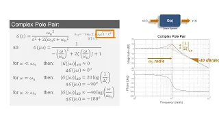
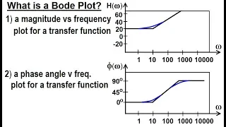
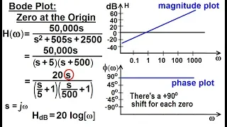
In electrical engineering and control theory, a Bode plot /ˈboʊdi/ is a graph of the frequency response of a system. It is usually a combination of a Bode magnitude plot, expressing the magnitude (usually in decibels) of the frequency response, and a Bode phase plot, expressing the phase shift. As originally conceived by Hendrik Wade Bode in the 1930s, the plot is an asymptotic approximation of the frequency response, using straight line segments. (Wikipedia).
In this video we introduce the concept of Bode plots including what they represent, how they are generated, as well as how to use Matlab tools to work with Bode plots. Topics and time stamps: 1:19 – Introduction 5:29 – Defining a Bode plot 8:42 – Demonstration with a real mass, spring, d
From playlist Control Theory
What Are Bode Plots? | Understanding Bode Plots, Part 2
Learn the principal characteristics of a Bode plot in this MATLAB® Tech Talk by Carlos Osorio. This video explains how a Bode plot describes the frequency response of a linear time-invariant system and the plot’s primary characteristics, such as the DC gain, roll-off rate, natural frequenc
From playlist Understanding Bode Plots
How to Build Bode Plots for Simple Systems | Understanding Bode Plots, Part 3
Learn how to build Bode plots for first-order systems in this MATLAB® Tech Talk by Carlos Osorio. A Bode plot describes the frequency response of a dynamic system and displays the magnitude and phase of the system response as a function of frequency in a logarithmic scale. You will learn h
From playlist Understanding Bode Plots
How to Build Bode Plots for Complex Systems | Understanding Bode Plots, Part 4
Learn how to build Bode plots for first-order systems in this MATLAB® Tech Talk by Carlos Osorio. A Bode plot describes the frequency response of a dynamic system and displays the magnitude and phase of the system response as a function of frequency in a logarithmic scale. You will learn h
From playlist Understanding Bode Plots
Why Use Bode Plots? | Understanding Bode Plots, Part 1
Learn how frequency domain analysis helps you understand the behavior of physical systems in this MATLAB® Tech Talk by Carlos Osorio. You will learn about Bode plots and how they are used by control engineers to gain insights into the behavior of dynamic systems. The Bode plot is a popular
From playlist Understanding Bode Plots
Bode Plots of Complex Transfer Functions
In this video we discuss how to generate a bode plot of a complex transfer function by decomposing it into the individual components. We then show how one can sketch the bode plot for each individual component and then linearly add them together to obtain the transfer function of the comp
From playlist Control Theory
Electrical Engineering: Ch 15: Frequency Response (17 of 56) What is a Bode Plot?
Visit http://ilectureonline.com for more math and science lectures! I will explain what is a Bode plot. A Bode plot is a tool that helps us understand the transfer function gain and the transfer function phase angle. http://www.ilectureonline.com/donate https://www.patreon.com/user?u=323
From playlist ELECTRICAL ENGINEERING 15 FREQUENCY RESPONSE
Electrical Engineering: Ch 15: Frequency Response (21 of 56) Bode Plot: Zero at the Origin
Visit http://ilectureonline.com for more math and science lectures! We will have a more detailed look at what the transfer function looks like for a zero on a Bode plot. http://www.ilectureonline.com/donate https://www.patreon.com/user?u=3236071 Next video in this series can be seen at:
From playlist ELECTRICAL ENGINEERING 15 FREQUENCY RESPONSE
Understanding and Sketching Individual Bode Plot Components
In this video we illustrate how 7 types of simple transfer functions contribute to a bode plot. We refer to these as ‘components’ and will cover the following: 1. Single real pole 2. Single real zero 3. Pole at the origin (integrator) 4. Zero at the origin (differentiator) 5. Pair of com
From playlist Control Theory
EE102: Introduction to Signals & Systems, Lecture 15
These lectures are from the EE102, the Stanford course on signals and systems, taught by Stephen Boyd in the spring quarter of 1999. More information is available at https://web.stanford.edu/~boyd/ee102/
From playlist EE102: Introduction to Signals & Systems
EE102: Introduction to Signals & Systems, Lecture 17
These lectures are from the EE102, the Stanford course on signals and systems, taught by Stephen Boyd in the spring quarter of 1999. More information is available at https://web.stanford.edu/~boyd/ee102/
From playlist EE102: Introduction to Signals & Systems
How to Visualize a Bode Plot of a Simulink Model
Learn how to visualize the Bode response of a Simulink® Model during simulation. Watch the steps involved in generating a Bode plot of a water tank system using the Model Linearizer app in Simulink. - Linearize Simulink Model at Model Operating Point: https://bit.ly/3TSroQv - Understandin
From playlist “How To” with MATLAB and Simulink
EE102: Introduction to Signals & Systems, Lecture 16
These lectures are from the EE102, the Stanford course on signals and systems, taught by Stephen Boyd in the spring quarter of 1999. More information is available at https://web.stanford.edu/~boyd/ee102/
From playlist EE102: Introduction to Signals & Systems
Electrical Engineering: Ch 15: Frequency Response (20 of 56) Bode Plot: The Constant Gain
Visit http://ilectureonline.com for more math and science lectures! We will example the first, also the easiest, factor of the Bode plot: The constant gain factor. http://www.ilectureonline.com/donate https://www.patreon.com/user?u=3236071 Next video in this series can be seen at: https
From playlist ELECTRICAL ENGINEERING 15 FREQUENCY RESPONSE